
Engineering deep dive · Ports, functions, specs, and selection traps
RF Isolator and Circulator are two of the most misunderstood passive components in microwave engineering. The core difference comes down to ports and function. An Isolator is essentially a three‑port Circulator with its third port terminated into a matched load. A Circulator is a non‑reciprocal signal router — it directs signals from one port to the next in a fixed circular order. An Isolator is a one‑way valve — it lets signal pass from input to output, but absorbs anything coming back the other way.
What It Is
Both RF Circulator and Isolator are passive non‑reciprocal devices built around ferrite materials. A Circulator typically has three or four ports and controls signal flow direction between ports. An Isolator has two ports and exists to isolate reflected signals.
How It Works
Both devices exploit the anisotropic properties of ferrite under a static magnetic bias field. A Circulator uses Faraday rotation or field‑displacement effects to force signals to travel in only one direction — clockwise or counter‑clockwise — from one port to the next. An Isolator is built by terminating the third port of a Circulator with a matched load (usually 50Ω). Any reverse‑direction signal entering the Isolator gets steered into that load and burned off as heat.
Why It Matters
These devices protect power amplifiers from reflected power damage (Isolator), enable shared‑antenna transmit/receive operation (Circulator as a duplexer), and improve overall system stability. Typical specs: insertion loss 0.3‑0.5dB, isolation 20‑40dB.
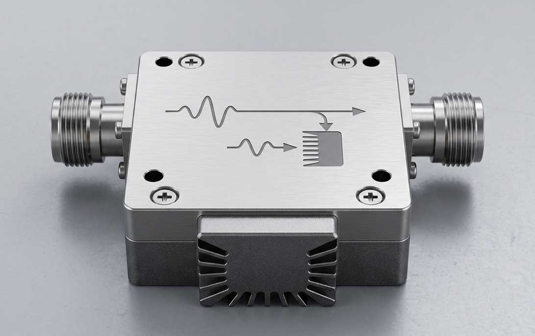
RF Circulator: A three‑port (or four‑port) passive device. A signal entering any port can only exit through the next adjacent port — not back to the port it came from, not to the other ports. For a clockwise circulator: Port 1 → Port 2, Port 2 → Port 3, Port 3 → Port 1.
RF Isolator: A two‑port device. It is literally a circulator with the third port terminated into a matched load (typically 50Ω). It allows signal to pass from Port 1 to Port 2 only. Any signal entering from Port 2 gets routed to the terminated Port 3 load and dissipated as heat.
The core of both devices is non‑reciprocity — signal transmission characteristics differ depending on direction. This comes from the ferrite material's gyrating magnetic field under an external bias magnet, which makes the signal path direction‑dependent.
Two operating modes:
Physical mechanism: A Circulator uses the TM₁₁ mode generated inside the ferrite. The incident wave splits into clockwise and counter‑clockwise rotating components. The counter‑clockwise component couples with the ferrite's magnetic dipoles and slows down; the clockwise component doesn't couple. This creates a spatial shift of the electric field null toward the isolation port — producing the circulation effect.
Circulator advantages:
Isolator advantages:
Typical performance numbers:
Identify the amplifier's operating band — e.g., 400‑430MHz, or 2.1‑2.3GHz. Select an Isolator that covers that band. Understand the trade‑off: broadband designs typically have lower isolation than narrow‑band ones.
Calculate the amplifier's maximum output power and the worst‑case reflected power from load mismatches (highest VSWR). The Isolator's internal load must be able to absorb 100% of the reflected power. If the load rating is insufficient, it will burn out and the device will fail.
Insertion loss should typically be ≤0.5dB — higher loss reduces system efficiency and generates heat. Isolation should typically be ≥20dB — lower than that and you're not protecting the amplifier effectively.
Pick the package type that fits your PCB space and assembly method: Coaxial, Drop‑In, SMT, or Waveguide.
Install the Isolator in‑line between the PA output and the antenna/load. In high‑power applications, the internal resonant absorber dissipates reflected energy as heat — you'll need proper thermal management (heat sink or forced air).
Yes, a Circulator with a load on port 3 becomes an Isolator. But slapping any 50Ω load onto a stock Circulator rarely gives you the isolation you expect. Dedicated Isolators have the third port precision‑matched for broader bandwidth and higher isolation than a generic load can provide.
In the worst case — a completely open output (VSWR = ∞) — 100% of the incident power gets reflected straight back into the Isolator's internal load. If that load isn't rated for full incident power, it will burn out instantly. Always size the load for 100% incident power, not average power.
Q1: What's the real difference between an RF Isolator and a Circulator?
Port count and termination. A Circulator is a three‑port non‑reciprocal device with a cyclic signal path (1→2→3→1). An Isolator is a Circulator with port 3 terminated into a matched load — turning it into a two‑port device that passes signal in one direction only and absorbs reverse power.
Q2: When should I use a Circulator vs an Isolator?
Use an Isolator when you need to protect a signal source from reflected power — typically at the output of a power amplifier. Use a Circulator when you need to share a single antenna between transmitter and receiver — it acts as a duplexer in radar and communication systems.
Q3: What's the typical insertion loss of an Isolator or Circulator?
High‑performance devices: 0.3‑0.5dB. General spec: ≤1dB. Loss generally increases with frequency.
Q4: How does a Circulator achieve unidirectional transmission?
The ferrite material, under a static bias magnetic field, creates a gyrating magnetic field that forces the RF signal to follow the rotation direction — it cannot travel backward. A useful analogy: like stirring pepper into water — the pepper can only move with the vortex, not against it.
Q5: Can ferrite Circulators/Isolators work below 65MHz?
The practical low‑frequency cutoff for ferrite devices is around 65MHz. Below that, you need active transistor‑based electronic Circulators — but these have narrow bandwidth and higher loss, and aren't suitable for duplexing applications.
RF Isolator and Circulator are not interchangeable. One is a load‑terminated variant of the other, but that termination changes everything — function, port count, application space, and power handling limits.
In the field, the most common failure is using the wrong device for the job — putting a Circulator where an Isolator is needed, or under‑specifying the load power on an Isolator. Both mistakes cause the same result: system failure and a bench full of burned components.
When you're specifying these devices, look at the full picture — insertion loss, isolation, power handling, load rating, and temperature stability. And if a supplier can't give you real test data across your operating band, move on. The data sheet tells you what they wish it could do. The test data tells you what it actually does.
Maniron tronics — Full‑range RF passive components for communication infrastructure: isolators, circulators, power dividers, directional couplers, combiners, duplexers, tappers, loads, and antennas. All products undergo full‑band testing with lot‑level traceability. Technical consultations and product inquiries welcome.
Теги :
У вас есть какие-либо вопросы ?
Позвоните Нам : +86 551 65329702